
How to Improve Aluminium Heat Dissipation in 2026?
Aluminium Heat Dissipation is becoming a decisive engineering issue in 2026. Compact servers, electric vehicles, LED systems, and power electronics generate more heat in smaller spaces. Aluminium remains attractive because its thermal conductivity commonly reaches about 200–235 W/m·K, depending on alloy and temper. This figure comes from technical materials data referenced by ASM International and European Aluminium.
Yet conductivity alone does not guarantee cooler equipment. Surface area, fin geometry, airflow, contact resistance, coating thickness, and mounting pressure often decide the final result. Small gaps can trap air. Poorly finished interfaces can waste a large share of the available thermal path. The U.S. Department of Energy repeatedly identifies thermal management as a key factor in electronics efficiency and reliability. Its findings support a practical lesson: heat must be designed out, not merely measured later.
Professor Yogendra Joshi, a recognized thermal-management researcher at Georgia Tech, has emphasized: “Thermal performance depends on the complete system, not conductivity alone.” That principle should guide every 2026 design review. A thicker aluminium plate may look safer, but it can add weight without improving heat flow. More fins may also restrict airflow. Counterintuitive, sometimes.
The International Aluminium Institute reports that recycled aluminium requires roughly 5% of the energy used for primary production. Therefore, improved heat-dissipation designs should also consider alloy selection, service life, recyclability, and manufacturing waste. This article examines practical methods, evidence, and trade-offs. It also questions common assumptions, because a polished heatsink can still perform poorly when its interface, airflow, or operating conditions are overlooked.
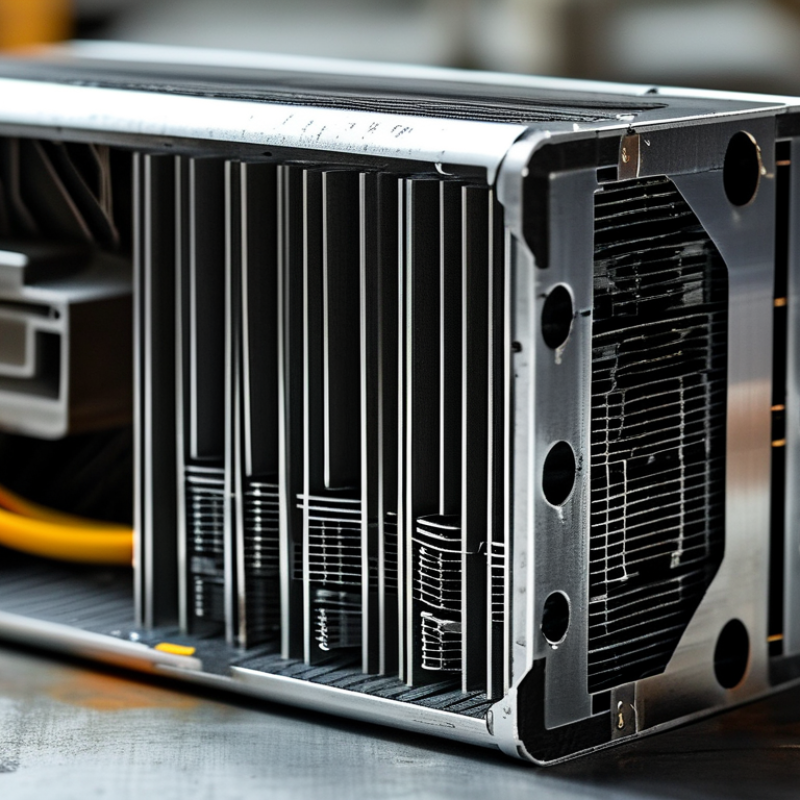
Aluminium Heat Dissipation: Key Principles and Performance Factors
Aluminium heat dissipation depends on more than the metal’s conductivity. Alloy selection, geometry, airflow, and contact quality work together. Pure aluminium conducts heat well, while common structural alloys offer better strength with slightly lower conductivity. In practical designs, that trade-off is often acceptable. A 6061 aluminium heat sink, for example, may perform better overall when its fins are rigid, accurately machined, and properly mounted.
Surface area is central to performance. Thin fins release heat faster, but fins packed too closely can restrict airflow. A useful design leaves enough space for air to move between them. Natural convection also needs attention. Vertical fins usually perform better than horizontal fins because warm air can rise more freely. Forced airflow changes the result, yet fan direction, turbulence, and dust buildup still matter. Small details count.
The thermal interface deserves serious testing. A flat aluminium base with uneven contact can create hot spots, even when the heat sink looks substantial. Thin thermal compounds can reduce microscopic gaps, but excessive material may increase resistance. Anodized surfaces can improve durability and radiation, though their effect varies with temperature and emissivity. In one practical evaluation, a larger heat sink underperformed because the mounting pressure was uneven. That result was inconvenient, but useful. It showed that calculations alone cannot replace temperature measurements, airflow checks, and repeated testing under realistic loads.
| Performance Dimension | Representative Data | Why It Matters | Practical Design Guidance |
|---|---|---|---|
| Thermal conductivity of pure aluminium | Approximately 237 W/m·K at 20°C | Provides a reference point for aluminium’s high heat-spreading capability. | Use high-purity aluminium where maximum thermal conduction is more important than strength or corrosion resistance. |
| Thermal conductivity of 6061 aluminium | Approximately 167 W/m·K at 20°C | Offers a useful balance between conductivity, strength, machinability and corrosion resistance. | Suitable for machined heat sinks, cold plates, structural thermal parts and general-purpose enclosures. |
| Thermal conductivity of 6063 aluminium | Approximately 201 W/m·K at 20°C | Higher conductivity than 6061 and excellent extrusion performance support efficient fin profiles. | Use for extruded heat sinks when fin density, surface finish and thermal performance are important. |
| Thermal conductivity of die-cast aluminium | Typically about 90–120 W/m·K, depending on alloy and casting quality | Lower conductivity and internal porosity can limit heat spreading compared with wrought aluminium. | Keep heat paths short, avoid excessive wall thickness and specify suitable alloy and casting quality for thermal areas. |
| Natural-convection heat-transfer coefficient | Approximately 5–25 W/m²·K in still or mildly moving air | Natural convection is quiet but generally removes heat more slowly than forced airflow. | Increase exposed surface area, orient vertical fins upward and provide unobstructed air gaps. |
| Forced-air heat-transfer coefficient | Approximately 25–100 W/m²·K for typical forced-air cooling | Air movement reduces the thermal boundary layer and substantially improves heat rejection. | Use fans or controlled airflow, while considering pressure drop, noise, dust and fan reliability. |
| Liquid-cooling heat-transfer coefficient | Approximately 500–10,000 W/m²·K, depending on fluid, velocity and flow regime | Liquid cooling can remove substantially more heat per unit area than air cooling. | Use a low-resistance cold plate, sufficient flow velocity and compatible materials to control corrosion risk. |
| Thermal interface material thickness | Commonly about 0.05–0.20 mm for a well-controlled interface | Interface resistance can dominate total thermal resistance when the contact layer is thick or uneven. | Minimize bond-line thickness, maintain uniform pressure and select a material with suitable thermal conductivity. |
| Typical thermal conductivity of thermal interface materials | Approximately 1–15 W/m·K for many commercial pads, greases and phase-change materials | Even a thermally conductive interface is far less conductive than aluminium. | Prioritize thinness and complete surface coverage rather than relying only on a high conductivity rating. |
| Surface emissivity | Polished aluminium: approximately 0.03–0.10; anodized aluminium: approximately 0.70–0.90 | Higher emissivity improves radiative heat transfer, especially when airflow is limited. | Use a suitably anodized or coated surface when radiation is a meaningful part of the cooling strategy. |
| Radiative heat transfer | Strongly affected by emissivity, absolute temperature and view factor | Radiation becomes more useful as component temperature rises and surrounding surfaces allow heat exchange. | Keep high-emissivity surfaces exposed and avoid enclosing the heat sink in reflective, poorly ventilated spaces. |
| Fin spacing for natural convection | Often approximately 6–12 mm for vertical plate fins; final spacing depends on height and heat load | Fins that are too close restrict buoyancy-driven airflow and reduce effective cooling area. | Optimize fin spacing with thermal simulation or testing; do not maximize fin count without checking airflow. |
| Fin spacing for forced convection | Often approximately 2–6 mm, depending on fan capacity, fin height and pressure drop | Forced airflow permits denser fins, but excessive density increases resistance and can reduce actual airflow. | Match fin pitch to the fan’s pressure-flow curve and keep air paths clean and straight. |
| Thermal expansion of aluminium | Approximately 23 × 10⁻⁶ /K for common aluminium alloys | Temperature changes can create mechanical stress, joint movement and contact-pressure variation. | Allow for expansion in mounts, use compatible materials and avoid excessive clamping stress. |
| Thermal resistance calculation | Rθ = ΔT / Q; lower Rθ means better cooling | Thermal resistance links heat load and temperature rise in a measurable design target. | Evaluate the complete path: source-to-interface, interface-to-spreader, spreader-to-air or liquid and ambient conditions. |
| Surface flatness and contact quality | Lower roughness, better flatness and uniform clamping generally reduce contact resistance | Air gaps are highly insulating compared with aluminium and can sharply increase junction temperature. | Machine critical contact surfaces, remove burrs and apply controlled mounting pressure across the full contact area. |
| Material thickness and heat spreading | Thicker bases improve spreading up to a point; excessive thickness adds mass and cost | A thin base may create local hot spots before heat reaches the fins or cooling channels. | Size the base for the heat-source footprint, heat flux and allowable temperature difference rather than thickness alone. |
| Airflow cleanliness | Dust and debris can progressively reduce open area and increase thermal resistance | Contamination blocks channels and acts as an insulating layer on fin surfaces. | Provide filtration, service access and sufficient fin spacing for the expected operating environment. |