Choosing a robotic grinding system is not just a matter of selecting a robot with enough payload. The right setup must match the part, abrasive process, production volume, and required finish. A small casting with rough seams presents different demands from a large, curved component with tight dimensional tolerances. Details matter.
This guide outlines seven practical considerations for comparing systems, from robot reach and force control to tooling, programming, and cell integration. Look closely at how the robot maintains contact across uneven surfaces. A steady spindle is useful, but it cannot compensate for poor fixturing or an unsuitable abrasive. Dust extraction and guarding also affect the working environment, maintenance needs, and overall cell design.
Robotic grinding can improve repeatability and reduce exposure to repetitive manual work, but results depend on the application. Parts may vary. Tool wear can change the finish, and an apparently simple process may need careful testing. That deserves attention. Before choosing equipment, define measurable targets for cycle time, surface quality, and acceptable variation. Then ask suppliers how they would validate those targets on representative parts—not only in a polished demonstration.
No single system fits every shop. These tips can help engineers and production teams identify trade-offs, ask more useful questions, and avoid buying features their process does not need. A careful evaluation may take longer. It is usually worth the effort.
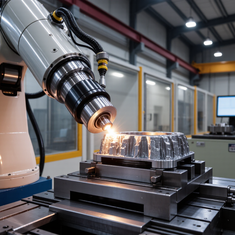
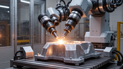
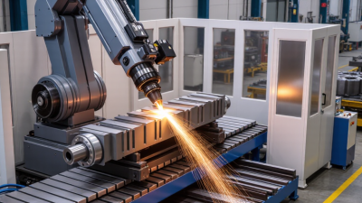
A robotic grinding system combines a robot arm, grinding spindle, abrasive tool, workholding fixture, controller, and safety equipment. Each part affects the finish. The robot positions the tool, while the spindle sets its rotation speed. Abrasive discs, belts, or wheels suit different materials and surface shapes. A rigid fixture keeps the workpiece steady; even slight movement can leave visible marks. Force sensing helps maintain contact as surfaces vary. Dust extraction also matters, especially when grinding produces fine particles.
Tip: Check how the system controls force and tool wear. Ask for sample parts made from your own material, not just a polished demonstration piece. Watch the tool path closely.
Choose components around the task, not an impressive-looking payload rating. A small part with curved edges may need a compliant tool and careful path planning. Large welds may need more reach and a tougher abrasive. In practice, setup and fixturing can take longer than expected. A tidy specification sheet can still mislead. I would verify cycle time, finish consistency, and abrasive life across several parts before committing. Some variation is normal; the important question is whether the system can detect and manage it.
Contact force depends on the abrasive, material, tool angle, and desired finish. These representative planning ranges illustrate why a force-control system should be selected and validated for the specific application; they are not universal operating limits.
Before choosing a robotic grinding system, describe the workpiece in measurable terms. Record its dimensions, weight, shape, and how firmly it can be fixtured. Include variations between parts, not just the ideal sample. A casting with uneven edges behaves differently from a flat, consistent panel. Small details matter: a narrow recess may limit tool access, while a thin edge can deform under pressure.
Tip: Match the abrasive and contact method to the material. Aluminum, steel, and composite parts can respond differently to heat and force. Define the finish with a measurable target, such as roughness, scratch direction, or allowable material removal. State which areas need grinding and which must remain untouched. A clear sample helps, but one sample may not show the full range of production variation.
Set acceptance criteria before trials begin. Note inspection methods, lighting conditions, and where measurements should be taken. A surface that looks smooth under workshop lights may still show deep scratches at an angle. No specification captures every odd corner, so plan a trial with representative parts and review the results carefully. If the finish varies across a part, adjust the process by zone rather than relying on one setting everywhere. Keep records of tool wear and cycle conditions; these details can explain changes that otherwise seem mysterious.
Robot reach should cover the full workpiece without forcing the arm to operate at its limit. Check the tool path at corners, deep cavities, and fixture edges. A long reach can help, but extended joints may reduce stiffness and make contact less consistent. Payload calculations should include the spindle, abrasive head, adapters, cables, and extraction hose—not just the tool’s listed weight. Small details matter. Review the robot’s load charts and wrist moment limits, then test the planned motion with the actual tooling. A digital simulation can miss hose drag or a fixture that blocks access.
Choose abrasives for the material, removal rate, and required finish. Coated discs may suit broad surfaces, while nonwoven wheels can help blend marks without cutting as aggressively. Match the spindle speed and contact pressure to the abrasive maker’s guidance; excess pressure can create heat, uneven wear, or a rough finish. Tooling should hold the abrasive securely and provide enough compliance for minor surface variation. Force control can help, but it will not fix a poor approach angle. There is no perfect recipe. Run sample parts, inspect scratch patterns and edges, and adjust one variable at a time. That process can feel slow, but it often reveals a mismatch before it spreads across a production batch.
Choosing a robotic grinding system starts with the part, not the robot. Record material, dimensions, surface requirements, and expected production volume. Measure how much parts vary. A fixture that works for one sample may fail when castings shift slightly. Include abrasive changes, dust extraction, and loading time in cycle-time estimates. Small delays add up.
Programming should account for contact force, tool angle, and abrasive wear. Use representative parts to test the path, then inspect edges and surface finish under consistent lighting. Keep the process adjustable. Real parts can surprise you. Safety planning needs the same care: assess access points, guarding, interlocks, dust collection, and maintenance tasks before installation. Operators should be able to clear routine faults without reaching into hazardous areas.
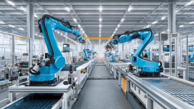
Integration often decides whether automation performs well beyond a demonstration. Confirm how the cell will exchange signals with upstream and downstream equipment. Plan space for conveyors, extraction ducting, tool storage, and safe service access. Track practical measures such as cycle time, rework, and abrasive life. A neat simulation can still overlook awkward part loading or frequent changeovers. That is worth revisiting early, even if the layout already looks finished.
A strong comparison starts with your own parts, not a polished showroom sample. Check seven things: finish consistency, cycle time, tool changes, reach around fixtures, abrasive use, dust extraction, and guarding. Run several batches, including parts with normal variation. Measure roughness and inspect edges under the same light each time. A fast cycle means little if rework rises. That is easy to miss.
Compare total cost over the system’s expected service life, not just the purchase quote. Include integration, tooling, operator training, maintenance, energy, and downtime. The International Federation of Robotics’ World Robotics 2024 report recorded 541,302 industrial robot installations worldwide in 2023. That figure shows broad adoption, but it is not a grinding-specific return-on-investment benchmark. Build your own estimate from measured cycle times and documented scrap rates. Keep assumptions visible; forecasts can look too neat.
Long-term support can decide whether a cell stays productive. Ask how quickly technicians respond, which spare parts are stocked locally, and whether software updates preserve validated process settings. Request a maintenance schedule and a clear handover for your staff. Talk with users running comparable materials and shifts, if possible. I would still treat one successful trial cautiously: abrasive wear, dust, and part variation may expose problems only after weeks of operation.
| Tip | What to Compare | Performance Check | Cost Consideration | Long-Term Support Check |
|---|---|---|---|---|
| 1 | Match the robot to the work envelope and payload | Check reach, wrist access, tooling mass, and grinding forces across the full path. Industrial robot repeatability is commonly specified in the hundredths of a millimeter, but that figure alone does not guarantee part accuracy or finish quality. | A larger robot or custom positioner can increase purchase and installation costs. Confirm that the selected payload includes the spindle, tool, cables, and any added compliance device. | Check local availability of replacement components, qualified service technicians, and documented maintenance procedures. |
| 2 | Test force control and compliance | For variable part geometry or finishing, assess whether the system maintains the required contact force. Compare force-sensing, compliant-tool, or passive spring options using representative parts and measurable finish criteria. | Force-control hardware and setup add cost, but may reduce rework and tool wear when part variation would otherwise cause uneven contact. | Ask how force sensors or compliance units are calibrated, inspected, and replaced, and whether calibration support is available on site. |
| 3 | Size the spindle and abrasive for the process | Compare spindle speed, power, torque, duty rating, and tool compatibility against the material and removal rate. Validate cycle time and surface quality in a sample run; higher power by itself does not ensure faster or better grinding. | Include abrasive consumption, spindle maintenance, and the cost of process trials—not only the spindle purchase price. | Confirm bearing and spindle service intervals, repair turnaround, and availability of compatible abrasives and replacement tooling. |
| 4 | Evaluate tool changes and process flexibility | Check whether the cell can handle the required abrasive types, tool sizes, and part families. Include tool-change time, tool identification, and the steps needed to verify a new process recipe. | Automatic tool changing can reduce manual intervention but adds hardware, controls, and maintenance. Compare its cost with the expected frequency of tool changes. | Ensure operators can safely load tools and that the supplier provides clear setup instructions, training, and support for recipe changes. |
| 5 | Plan dust extraction and operator safety | Assess enclosure design, extraction capture at the grinding point, filtration, noise, and access for cleaning. Dust-control requirements depend on the material and applicable workplace rules; metal dust may also require specific fire or explosion-risk assessment. | Budget for extraction equipment, filters, ducting, enclosure modifications, and routine filter replacement. These items can be missed when comparing robot-only quotations. | Request maintenance schedules, filter-change guidance, safety documentation, and support for future risk assessments or process changes. |
| 6 | Verify integration, cycle time, and uptime | Run a production-representative acceptance test that includes loading, clamping, grinding, tool changes, inspection, and unloading. Record good-part cycle time and the causes of interruptions, rather than relying on motion time alone. | Include fixturing, safety systems, programming, utilities, installation, commissioning, and operator training in the total project estimate. | Agree on response times, escalation contacts, software backups, remote-support access, and responsibility for troubleshooting third-party equipment. |
| 7 | Compare total cost of ownership and serviceability | Estimate annual operating hours, abrasive use, energy, planned maintenance, downtime, and expected part volume. Recalculate the cost per good part using the same production assumptions for every system under review. | Compare the purchase price with installation, consumables, maintenance, training, and replacement parts over the intended service period. A low initial price may not mean a lower lifetime cost. | Review warranty terms, parts availability, service coverage, training options, and the process for software updates and future system upgrades. |
Evaluation note: Performance and cost outcomes vary with material, part geometry, finish requirements, production volume, and site conditions. Treat the checks above as selection criteria and validate them with representative parts, a documented acceptance test, and a project-specific cost model.